moogerfooger
USER'S MANUAL
12-STAGE PHASER
WELCOME
Welcome to the world of the Moogerfooger® Effects Plug-ins, a re-invention of Bob Moog’s classic analog effects modules using DSP artistry to bring the legendary performance and musicality of the original hardware effects to your digital music production environment.
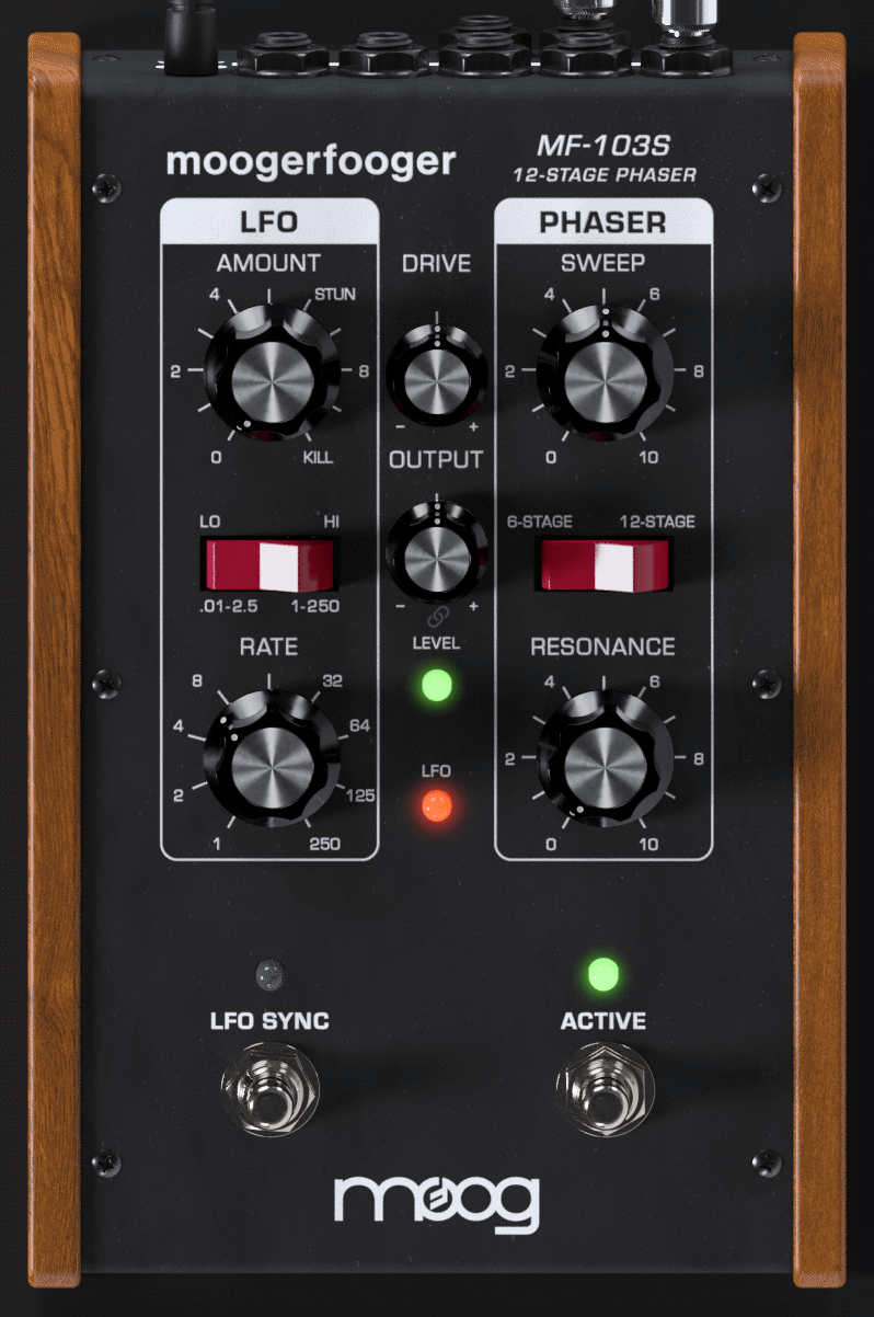
The MF-103 12 Stage Phaser, introduced in 1999, was a direct descendent of the original Moog modular synthesizers and professional rack effects. It contained two complete modular functions: a 6-stage/12-stage voltage-controlled Phaser and a voltage- controlled wide range Low Frequency Oscillator (LFO). All four performance parameters were voltage-controllable, which allowed the user to use expression pedals, MIDI-to-CV converters, or any other source of control voltages to 'play' the MF-103.
The MF-103S retains this same design, with all parameters able to be played, tweaked, automated and modulated to create lively and truly musical performances. The MF-103S captures not only the spaced-out, retro-futuristic sound of the original, but also the organic way in which the parameters interact to create a musical playing experience. Adding a Moogerfooger effect to your sound invites exploration and experimentation to bring your unique musical expressions to life.
GETTING STARTED
In your Digital Audio Workstation (DAW) software, place the MF-103S plug-in on an instrument or audio track.
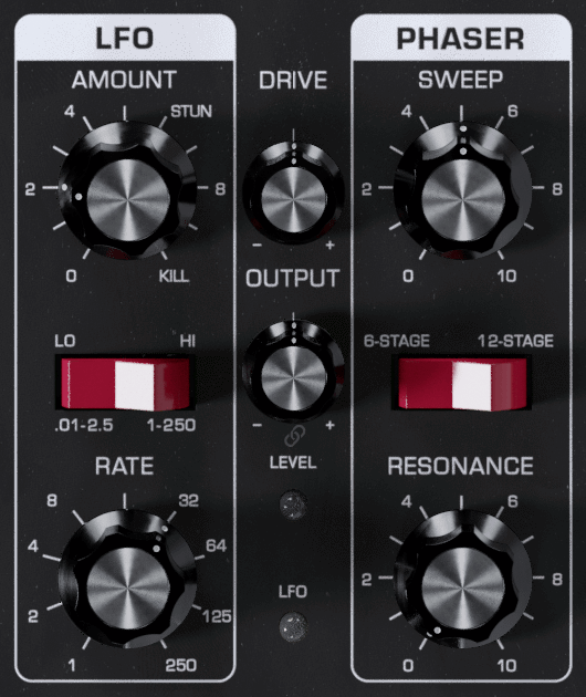
Set the MF-103S panel controls as follows:
RATE – 32
AMOUNT – 2
SWEEP – 5
RESONANCE – 0
Left Switch – LO
Right Switch – 6-STAGE
With audio playing on that track so you can hear the effect, listen to how the MF-103S affects the quality of the sound. You will hear a distinct slow variation. Note that the AMOUNT knob changes the strength of the variation and the RATE knob changes the speed of the variation.
Try turning up the DRIVE knob to add warm, analog-style saturation to your sound. If adding DRIVE makes the audio too loud, turn down the OUTPUT knob to dial it back to the desired level. A small LINK button below the OUTPUT knob will link the DRIVE and OUTPUT controls, to maintain a constant audio level automatically when either DRIVE or OUTPUT is adjusted.
In the next sections we'll explain exactly how a phaser works and what the LFO does. For now, get a feel for the controls by experimenting with different settings.
FREQUENCIES, FILTERS, AND PHASERS
Let's start with some definitions. Please read this section carefully, as it will help you to understand the basic ideas behind the MF-103S Twelve-Stage Phaser.
Sound is a vibration of the air. The speed of vibration is called the frequency. It is measured in Hertz (Hz). One Hz is one vibration per second. We hear vibrations from 20 Hz to 20,000 Hz.
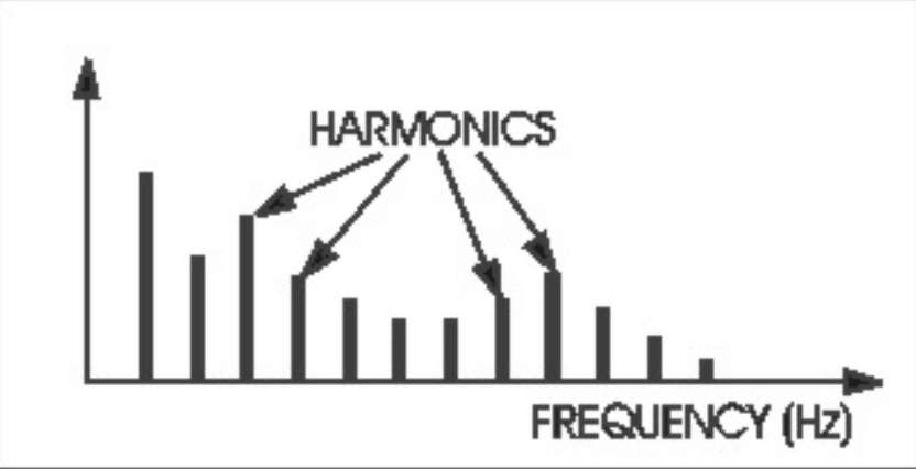
Musical sounds generally have many frequency components. They're called harmonics, or overtones, or partials. They are what give a sound its characteristic tone color, or timbre. A graph showing the strength of each of a sound’s harmonics is called a spectrum.
A filter, or equalizer, is a signal-modifying device that colors a sound by emphasizing some parts of the audio spectrum and attenuating (cutting down) other parts. In general, a filter or equalizer has a ‘quality’ of its own which is superimposed on the tone color of the original sound. Some types of filters (like the bass and treble controls on your sound system) have subtle, gentle effects on a sound’s timbre. Other types of filters have stronger and more dramatic effects, and are frequently used as vital elements in the music-making process. Strong filters include phasers, flangers, and wah-type resonant filters.
A graph showing what a filter does is called the filter’s frequency response. The horizontal axis is frequency. The vertical axis is the filter’s gain. A gain of “1” (unity) means that, at that frequency, the output of the filter is just as strong as the input. A gain of less than unity means that the filter’s output is attenuated at that frequency, while a gain of greater than unity means that the output is actually greater than the input.
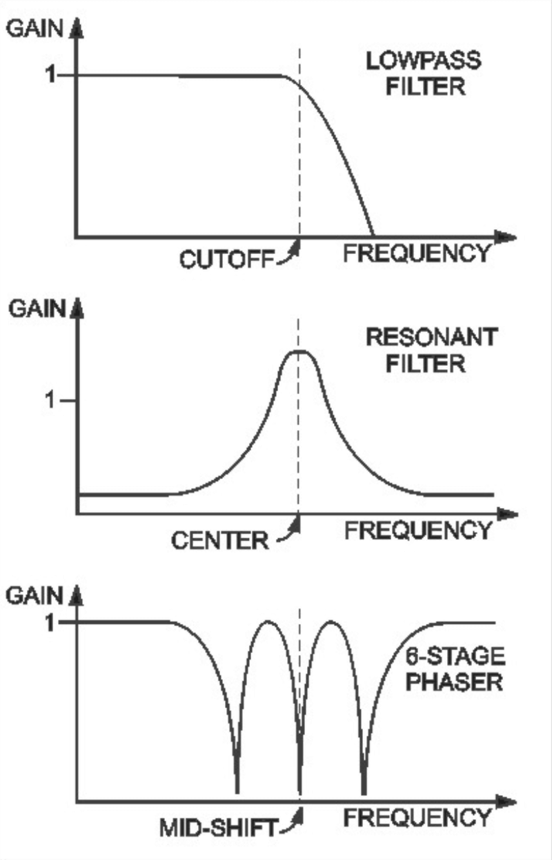
This figure shows examples of the frequency response characteristics of three common types of filters: (a) a lowpass filter, which passes frequencies without attenuation up to a so-called ‘cutoff frequency’, and attenuates the frequencies above cutoff; (b) a resonant filter, which emphasizes frequencies around the filter’s ‘center frequency’, and (c) a six-stage phaser, which has three dips (notches), the middle one of which is at the so-called ‘mid-shift’ frequency. All three of these filter types are widely used in contemporary music performance. Each of them has its own distinct sound, a large part of which is directly related to the shape of its frequency response graph. The first two types are embodied in the Moogerfooger MF-101S Lowpass Filter, while the six-stage phaser happens to be one of the modes of your MF-103S.
TOURING THE PANEL FEATURES
Phase Parameters
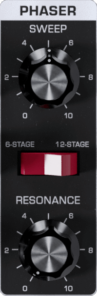
The following phaser parameters are under your control in the MF-103S:
MODE - 6-STAGE or 12-STAGE, selectable by the right-hand rocker switch.
OUTPUT MODE - MAIN (MAIN audio output on both left and right channels), MAIN & AUX (MAIN output on left channel, AUX output on right) or AUX & MAIN (vice versa). Output modes found in SETTINGS menu - see below.
RESONANCE - Changes the height and sharpness of the frequency response peaks. Use the RESONANCE panel control and/or the RESONANCE pedal control jack.
SWEEP - Moves the frequency response pattern through a six-octave range. Use the SWEEP panel control and/or the SWEEP pedal control jack.
We’ll now use frequency response graphs to show how each of these parameters affects your MF-103S frequency response.
We will always start with the ‘basic’ panel setup, which is:
AMOUNT - 0 (minimum LFO modulation)
SWEEP - 5 (middle of the range)
RESONANCE - 0 (no resonance)
Right-hand Rocker Switch - 6-STAGE
You may want to experiment with the panel controls and switches as we discuss each of the parameters.
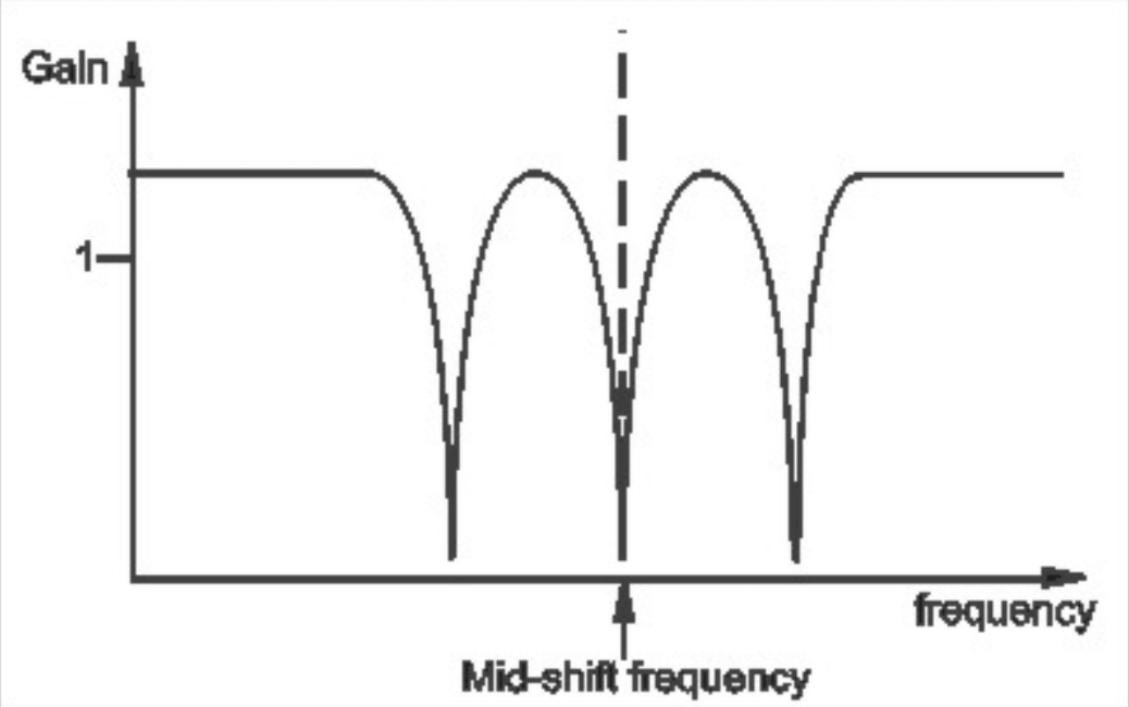
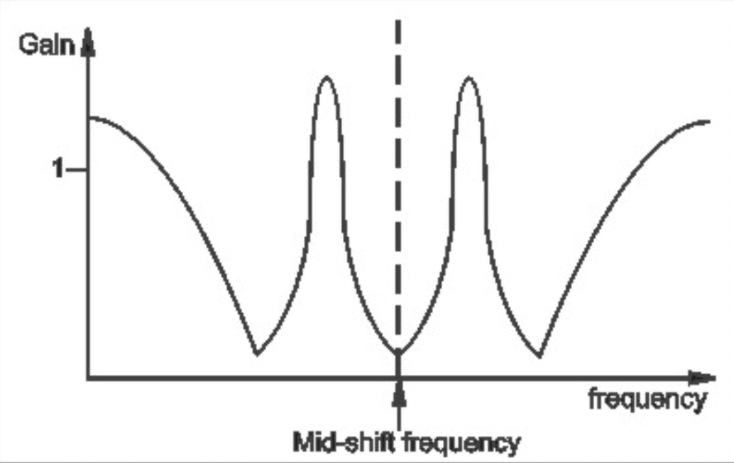
BASIC SETUP: This figure shows the MF-103S’s basic frequency response, the response that you hear when the panel controls are set up as in the basic setup. The mid-shift frequency is a little more than two octaves above middle C, and there are about two-octave intervals between adjacent dips.
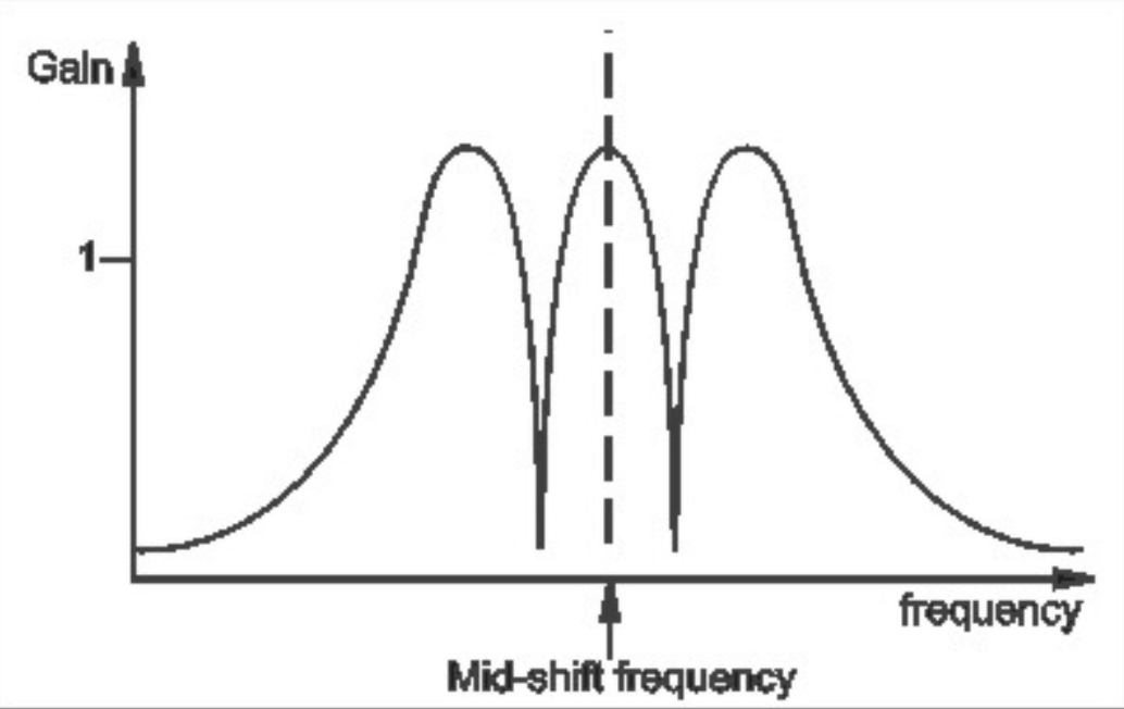
AUX OUTPUT: This figure shows the frequency response that you get when you start with the basic setup, and then listen to the AUX Output rather than the Main AUDIO Output. You can accomplish this by going to SETTINGS and choosing the MAIN & AUX Output Mode, then switching between soloing the left channel (MAIN) and right channel (AUX).
Note that the frequency response is the opposite of the previous figure. That is, the peaks of the AUX OUTPUT are at the same frequencies as the dips of the MAIN OUTPUT, and vice versa. The sound is similar, except that there is distinctly less sound energy at very low and very high frequencies. (We’ll say more about the AUX Output when we talk about using both audio outputs together as a stereo pair.)
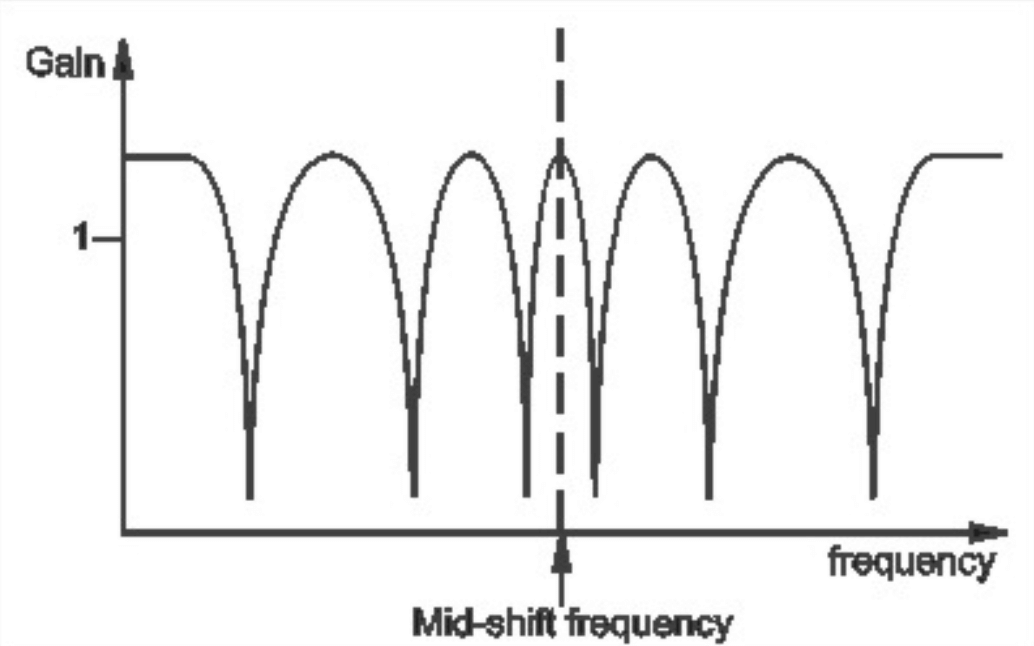
12-STAGE: This figure shows the frequency response that you get when you start with the basic setup and then switch the right-hand rocker switch to 12-STAGE. The mid-shift frequency has not changed, but now there are six dips, and the intervals between adjacent dips are half as wide. The quality is distinctly different from 6-stage.
RESONANCE: This figure shows the frequency response that you get when you start with the basic setup and then turn the RESONANCE control up to 10. The positions of the peaks and dips have not changed, but the peaks have become higher and sharper. This gives the phaser a quality similar to an array of highly resonant filters
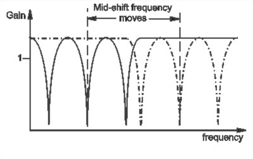
SWEEP: Finally, this figure shows what happens when you start with the basic setup and then turn the SWEEP control through its range. Technically speaking, the entire frequency response moves back and forth horizontally. Musically, you hear the classic phaser “whooshing” sound as different frequency bands of your instrument signal are alternately emphasized and then attenuated.
The phaser parameters are independent of one another. This means that you can set them in any combination that you wish. There is no such thing as a “wrong” combination of settings of the MF-103S, so you can experiment all you like to find new, exciting effects for your music.
The LFO (Low Frequency Oscillator)
LFO stands for Low Frequency Oscillator. LFO’s are generally used to create slow modulations such as vibrato and tremolo in electronic music equipment. The LFO in your MF-103S is an extremely wide-range voltage-controlled oscillator which modulates the phaser’s SWEEP parameter. This enables you to vary the SWEEP automatically at speeds from one cycle every 100 seconds (0.01 Hz), to 250 times a second (250 Hz). At the slowest speeds, the change is so subtle and gradual that it is barely perceptible. At speeds of, say 0.1 Hz to 2 Hz, you get a wide range of classic “whooshing” phaser effects. From about 2 Hz to 10 Hz, you’ll find the vibrato and tremolo effects. At frequencies above 20 Hz, the variation is in the audio frequency range and you get effects similar to ring modulation.
The RATE control varies the LFO speed over a 250:1 range. When the left switch is on LO, the RATE control varies the speed from 0.01Hz to 2.5 Hz; when the left switch is on HI, the RATE control varies the speed from 1Hz to 250 Hz.
The LFO indicator gives a visual indication of the LFO speed.
The AMOUNT control varies the depth of phaser modulation, from barely perceptible to the full sweep range of the phaser.
With LFO SYNC engaged the LFO will sync to the master tempo of your DAW project. The LFO RATE control will then be locked to musical divisions of your project tempo. The LFO SYNC LED will light up green when sync is engaged.
The Audio Level Controls

The DRIVE control adjusts the signal level at the phaser circuit input. With this control you can set the right input level for virtually any instrument or line-level signal source. Turn this control counterclockwise for strong input signals, and clockwise for weaker sound sources.
The LEVEL light tells how strong the input signal is after being adjusted by the DRIVE control. As the signal level increases, the light goes from off, to green, to yellow, and finally to red. Very weak signals do not light up this light at all. When the light is green, the signal is below the level that results in audible distortion. When the light is yellow, some low order distortion may be audible, giving the sound a subtle warm analog quality. When the signal is strong enough to drive the light into the red, the distortion at the output becomes stronger and more distinctly audible. Watch this light when you set the DRIVE control for the desired effect.
By clicking the LINK button next to the OUTPUT knob, you can link the DRIVE and OUTPUT knobs to move in opposite directions while adjusting one of them. You can turn up DRIVE to distort the input and introduce harmonics, while, with LINK enabled, the OUTPUT will simultaneously turn down to keep the overall level consistent.
The OUTPUT LEVEL control adjusts the strength of the phaser signals that appear at the MAIN and AUX outputs. Use this control to balance the phaser signals with the bypassed signal. Note that neither the DRIVE nor the OUTPUT LEVEL controls affect the strength of the bypassed signal.
Switches
LFO SYNC – Enables the LFO rate to sync to the project tempo. When the LFO SYNC light is on, the LFO RATE knob selects beat-synchronized divisions of the master tempo for the LFO rate. When the LFO SYNC light is off, the LFO is free-running, and the RATE knob sets the LFO speed in Hz (cycles per second).
ACTIVE – Controls whether audio input is sent into the effect. When the ACTIVE light is green, the effect is active. When the ACTIVE light is off, the audio input is passed directly to the output and is not sent into the effect.
NOTE: When the effect is not active, the CV outputs still continue working, to fully disable the pedal, use the bypass feature that your DAW provides
Using Both Audio Outputs Together
If you listen to just the main AUDIO output (OUTPUT MODE set to MAIN - see SETTINGS section below) will hear the classic ‘comb filter’ sound that arises from the characteristic phaser frequency response.
However, if you feed the AUDIO output to one speaker and the AUX output to another speaker, the two outputs together will not have peaks and dips in the overall frequency response. Instead, some parts of the sound spectrum will be coming from one speaker and other parts will be coming from the other speaker.
As the LFO modulates the phaser, the sound will seem to swirl around in space. The MF-103S lets you easily set this up via the OUTPUT MODE setting - see the SETTINGS section below. This is a terrific way of creating a stage-filling ambience from any sound source. It is also a great way to simulate a rotating speaker.
ADVANCED PLUG-IN FEATURES
The MF-103S offers additional functionality beyond the panel controls. To access, click the Settings icon ![]() in the top right of the plugin window. Click the row of CV jacks across the top of the pedal or the "CV" button next to the Settings icon to display the “back panel” of the MF-103S, showing the modulation input controls.
in the top right of the plugin window. Click the row of CV jacks across the top of the pedal or the "CV" button next to the Settings icon to display the “back panel” of the MF-103S, showing the modulation input controls.
Modulation Inputs
The original Moogerfooger effects provided input jacks for voltage control of the parameters, using expression pedals or other control voltage (CV) sources connected in classic modular synth style. The MF-103S brings this dynamic connection concept to the world of plug-ins, by providing virtual “CV Ins” which you can connect between any instances of any Moogerfooger Effects Plug-ins within your project.
NOTE: CV connections are stored in your DAW project, but not in the presets of each Moogerfooger Effects Plug-in.
The MF-103S offers CV Inputs to modulate LFO Rate [RATE], LFO Amount [LFO AMT], Resonance [RES], and two separate inputs for sweep - [SWEEP] sweeps the first 6 stages of the phasing circuit, while [SWEEP2] sweeps the second section of 6 stages and is only active when in 12 STAGE mode. Click on one of these CV IN jacks to see the connection options which are available.
TIP: As with the original Moogerfoogers, you can connect a pedal to itself to create more interesting sonic interactions than what's available on the front panel!
A list of all Moogerfooger Effects Plug-in instances which are active will appear in the drop-down menu, as well as the modulation sources they provide. Each plug-in instance is identified on this menu by a unique, randomly generated four-letter code. The same code is displayed on the “back panel” UI of the plug-in itself, in the lower right corner of the CV Input jack panel. This allows you to distinguish between multiple instances of the same plug-in. Choose any modulation source to make a connection.
The strength of the selected modulation is controlled by a bipolar knob below each CV IN jack, with zero (no modulation) in the center, increasing positive modulation if you turn the knob to the right, and increasing negative modulation if you turn the knob to the left.
TIP: Double clicking on the attenuator knob will reset it to zero.
Above the list of Moogerfooger Effects Plug-in instances are a handful of additional options and input sources:
- None - will remove any connections currently made to this CV input.
- Bipolar - will be available as an option if the chosen modulation source (an LFO for example) can be bipolar - centering the modulation around the current knob value.
- DC - provides a DC offset that you can scale with the associated attenuator. Since the CV attenuator itself can be automated or MIDI mapped, you can use this like an expression pedal. It will provide the same range of automation/modulation to a parameter regardless of any presets you choose.
- Side Chain - allows you to use an independent audio signal from another track as a modulation input. You can select either the Left or Right Input from stereo signals. Your host software will see the Side Chain Input as an additional input to the plug-in, which you can connect to the audio source of your choice.
NOTE: The CV side chain is designed to take DC-coupled analog or digital CV signals - regular audio signals might yield surprising results.
Visualizing Modulation
Making a CV connection will insert a virtual 1/4" cable into the top of your Moogerfooger (which can also be seen when you expand to see the back panel by clicking "CV" or the row of jacks across the top of the pedal). The incoming modulation signal will be seen in yellow on the connector. Additionally, the knob corresponding to the parameter being modulated (if present - not all parameters have a corresponding knob) will show a white circle indicating the current value due to modulation.
Settings
OUTPUT MODE
The MF-103S allows for immediate routing of the MAIN and AUX audio outputs to create stereo effects as in the original MF-103. With OUTPUT MODE switched to MAIN, the MAIN audio output will appear in both the left and right channels. Switched to MAIN & AUX, the MAIN audio left channel output will be routed to the left channel and the AUX output right channel will be routed to the right channel. When set to AUX & MAIN, the AUX audio left channel output will be routed to the left channel and the MAIN output right channel will be routed to the right channel.
LFO TYPE
The MF-103S is a true stereo effect, while the original MF-103 was a mono effect with a single signal path but two related outputs. The MONO setting emulates the original sound of a single monophonic LFO adjusting the SWEEP, while the STEREO setting phase inverts the LFO for right channel, allowing the stereo imagery of your source material to provide extra dynamics and detail to the resulting sound.
Additional UI Interactions
Double-click any control to reset it to its default position.
Hold the CTRL key while adjusting any knob for more precise fine-tuning.
PRESETS
In addition to your host software’s plug-in preset management system, the MF-103S provides an easy-to-use, built-in browser for selecting and saving presets.
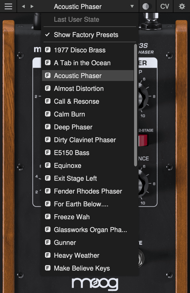
The currently selected preset name is shown at the top of the plug-in UI window. Click the left and right arrows to the left of the preset name to scroll through the preset list. Click the down arrow to the right of the preset name to expand the list and view all presets.
Last User State
The top option on the preset drop-down menu is Last User State. If you load a preset at a time when you had made changes to the plug-in settings which were not saved, your unsaved changes are automatically saved as the Last User State. This allows you to easily compare an existing preset with some new settings which you are still dialing in, or to go back after a preset change without losing your work. Only the most recent unsaved User State is captured in this way. An unsaved User State is indicated by an asterisk (*) to the left of the active preset name.
Show Factory Presets
Some people love the convenience of factory presets; others prefer to use only their own custom settings in their music. You can choose to hide the factory presets and show only your own original presets in this drop-down list by unchecking Show Factory Presets. If Show Factory Presets is checked, then all presets including the factory set will appear in the list. Factory presets are indicated by an F icon to the left of the preset name.
Compare Switch
Directly to the right of the preset drop-down is the Compare switch, which switches between the last loaded state and the last changed state. Load a preset, play around with it, and then click the Compare switch to toggle between the preset loaded and your most recent modifications to it.
Presets Menu
The Presets Menu is located in the top left corner of the plug-in UI window. Click the ![]() icon to show the Presets Menu. The following options are available:
icon to show the Presets Menu. The following options are available:
- Init Preset – creates a new INIT preset as a starting point for sound design.
- Save Preset – saves the current state to the currently-active preset. Overwrites the previous state of that preset.
- Save Preset As… – saves the current state as a new preset with a new name.
- Delete Current Preset – deletes the currently-active preset. Factory presets cannot be deleted in this way.
NOTE: You can also drag and drop preset files onto the plug-in UI to import them automatically.
- Export State - allows you to choose any folder in your computer’s file system and save the current plug-in state as a new preset in that location (Save Preset and Save Preset As will automatically place saved presets in the plug-in’s own Presets folder).
- Open Presets Folder - opens the plug-in’s Presets folder on your system’s desktop (Finder or File Explorer).
- Open Manual - opens this manual in your web browser.
- Contact Us For Help - opens the Moog Music customer service website.
SUPPORT
Moogerfooger Effects Plug-ins are designed for macOS 10.13 / Windows 10 systems or newer.
VST3, AudioUnits, and AAX plug-in formats are supported.
Should you experience any issues with your Moogerfooger, please contact [email protected].