moogerfooger
USER'S MANUAL
FREQBOX
WELCOME
Welcome to the world of the Moogerfooger® Effects Plug-ins, a re-invention of Bob Moog’s classic analog effects modules using DSP artistry to bring the legendary performance and musicality of the original hardware effects to your digital music production environment.
The MF-107 Freqbox, introduced in 2007, was a direct descendent of the original Moog modular synthesizers. It contained several complete modular synth functions: a voltage-controlled oscillator (VCO) with variable waveshape, capable of being hard synced and frequency modulated by the audio input, and an envelope follower which allowed the dynamics of the input signal to modulate the frequency of the VCO. In addition, the amplitude of the VCO was controlled by the dynamics of the input signal, and the VCO could be mixed with the audio input. All performance parameters were voltage-controllable, and control voltage outputs meant that the MF-107 could be used with other Moogerfoogers or voltage controlled devices like the Minimoog Voyager® or Little Phatty® synthesizers.
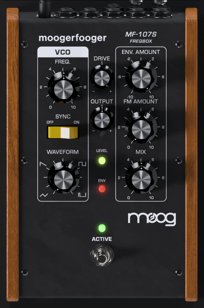
The MF-107S retains this same design, with all parameters able to be played, tweaked, automated and modulated to create lively and truly musical performances. The MF-107S captures not only the jagged, freaky sounds of the original, but also the organic way in which the parameters interact to create a musical playing experience. Adding a Moogerfooger effect to your sound invites exploration and experimentation to bring your unique musical expressions to life.
The Story Behind The FreqBox
Back in 2004, I had an idea for an oscillator that could hard sync to any input signal. Thinking that this might be a really cool and unique idea, I sketched it up and brought it to Bob Moog. I asked him if such an idea would be feasible. He looked me in the eye and produced one of his famous belly-laughs. He pointed over to our engineering technician at the time, Mark Kline. Mark had brought him this same idea a week or so earlier and had already begun building a feasibility prototype. I compared my sketch to the plans for the prototype. Lo and behold they were the same except for a few minor differences – all without either of us discussing this idea with each other! Bob loved this kind of occurrence, as he felt it revealed the interconnectedness of all things. He said the idea "must be in the air".
Mark soon left Moog Music to pursue a career in architecture, and we put aside "The Big Sync", as we called it then, to work on other projects. In 2006 it was time to revisit the design and add a few things, like the dynamic control of the oscillator volume, envelope follower modulation of the VCO and frequency modulation from the input signal, and the FreqBox was born. In Bob’s honor, I recommend connecting with your new Moogerfooger and exploring the outer regions of its sonic space. Enjoy!
Steve Dunnington,
Moog Music Inc.
2007
GETTING STARTED
In your Digital Audio Workstation (DAW) software, place the MF-107S plug-in on an instrument or audio track.
Set the MF-107S panel controls as follows:
FREQ – 4
WAVEFORM – SQUARE
ENV AMOUNT – 5
FM AMOUNT – 5
MIX - 5
Sync Switch – ON
With audio playing on that track so you can hear the effect, listen to how the MF-107S affects the quality of the sound. The most predictable results will come from playing single note riffs or melodies. This is especially true when the SYNC switch is ON. To hear more of the effect, increase the MIX setting.
For your first experiment, try turning the FM AMOUNT down. The effect will now sound smoother. Now try turning the FM AMOUNT all the way up, and turn the SYNC OFF. You’ll get a sizzly sound that is not clearly pitched. Turn the WAVEFORM down all the way and the effect gets less sizzly. As you turn the WAVEFORM control back up you’ll hear the sound become increasingly complex. Now try turning FM AMOUNT back down, and turn the ENV AMOUNT control to 0 (noon). When you play you’ll hear just the VCO at a single pitch.
The FreqBox has a lot more possibilities once you understand how it works. If you want to explore the FreqBox further before reading the manual, dive in to the Basic Applications section. It contains simple diagrams and descriptions of ways to setup the FreqBox. If you want to know about the Theory of the FreqBox, it’s covered in the section called FreqBox Theory.
BASIC APPLICATIONS
The following are diagrams of basic settings of the FreqBox. They are good staring points for learning how to use the FreqBox. For each setup, set the knobs on your FreqBox to the position shown. Adjust the DRIVE and OUTPUT level controls to match your input signal. Make sure the ACTIVE LED is GREEN to hear the effect.
Basic Sync Setup

This setup is best used with a MIDI controller (or automation in your DAW) set up akin to an expression pedal controlling the FREQ input and clean, single note lines. The controller can be used to sweep the frequency of the VCO slowly for slow harmonic sweeps, or quickly and rhythmically for an effect reminiscent of a wah wah. Use the controller to keep the VCO frequency above the note that you are playing. This is the basic setup for a classic hard sync sound.
Sync + FM
This setup is the same as the previous, but adds a dose of FM, which gives the sound an extra bit of growl, especially when the frequency of the VCO is swept with the FREQ control.
Auto Sync Sweep
This setup uses the dynamics of your playing to modulate the frequency of the VCO using the envelope follower. Hard playing causes the frequency to go up and you get more sweep of the VCO from the envelope follower. This is a really good setup to use with guitar, reminiscent of an auto-wah type of effect. The key to this setup is in setting the DRIVE control (not too much red showing on the Level indicator) and the ENV AMOUNT control. Using a MIDI controller for hands on control of the frequency sounds great with this setup.
Drone
This is a fun setup for modal jams or morning ragas – it uses just the sound of the VCO set to one frequency tuned to the key that you’re playing in. If you’re in A, just tune the VCO to A with the FREQ control. The drone sound can be fattened up if detuned a little bit from a bass note in the key. Setting the MIX control is important for a nice balance between the instrument sound and the VCO sound.
Foot Theremin

This is basically the same as the previous setup with the addition of a controller to control the VCO frequency. It’s difficult to control the frequency of the VCO precisely with a MIDI controller, but quite fun to attempt. Try playing staccato for synth-like bleeps and bloops, or play sustained tones with wild FREQ movements for instant psychedelic freakout sounds à la the "Whole Lotta Love" breakdown (just add a little echo).
FM Gongs
This is a setup that just uses FM for sounds somewhat reminiscent of gongs. It works well with slow, guitar-like signals plucked and allowed to fade out. Don’t play too hard or the gongs may sound flatulent.
FM Sizzler
This is a weird one – good for otherworldly synth-type sweeps. As with previous examples, use a controller to control the VCO frequency. Try sweeping the frequency down slowly as you play – you’ll hear a symphony of sidebands swirling around...
Electro Drumz
Start by connecting the ENVELOPE output into the ENV AMOUNT input via CV (see 'Modulation Inputs' section below for more details). For the best results, play a sound with a strong attack and a quick fade, like a very muted guitar string plucked hard with a pick. This gives a REALLY sharp sweep of the VCO frequency by the envelope follower so that you can make really percussive sounds. The brightness of this percussive sound is controlled by how hard you play. A controller connected to FREQ allows you to sweep from deep sounding percussive sounds in the low range to really high pitched sizzly sounds in the top range.
FREQBOX THEORY
Let's start with some definitions. Please read this section carefully, as it will help you to understand the basic ideas underlying the FreqBox.
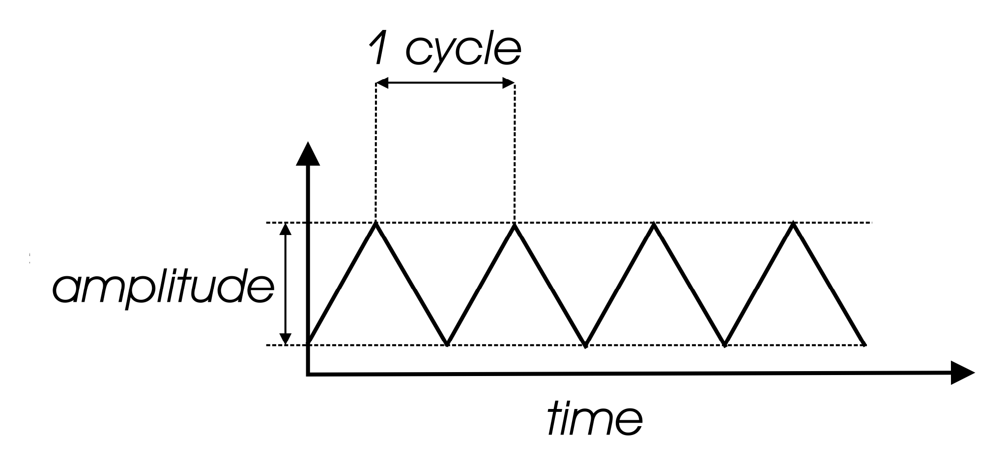
Sound is a vibration of the air. The speed of vibration is called the frequency. It is measured in Hertz (Hz). One Hz is one cycle per second. We hear vibrations from 20 Hz to 20,000 Hz. The lowest A on a piano is usually tuned to 27.5 Hz, and the highest C is tuned to 4186Hz. Each time you double a frequency, you hear a change of an octave. So the A’s on a piano are tuned from low to high to 27.5 Hz, 55 Hz, 110 Hz, 220 Hz, 440 Hz, 880 Hz, 1760 Hz, and 3520 Hz. That’s seven octaves. The loudness of a sound is called its amplitude. This relates to the strength of the vibration in the sound.
Different instruments playing the same pitch sound different, like an oboe and a violin playing A440. That’s because musical sounds generally have many frequency components. They're called harmonics, or overtones, or partials. The harmonics of a pitched musical sound are related to the pitch we hear, called the fundamental, by simple relationships, 1X (fundamental, or first harmonic) 2X (2nd harmonic), 3X (3rd harmonic), 4X (4th harmonic), 5X (5th harmonic), 6X (6th harmonic), and so on. These relationships define what we call the harmonic series. The presence and strength of different harmonics is what gives a sound its characteristic tone color, or timbre. We can represent a musical sound as a waveform. The waveform is a time graph of the actual shape of the vibration.
The waveform of a single harmonic is called a sine wave. It is the simplest type of periodic vibration there is. If you listen to a 500 Hz sine wave, you hear a pitch nearly an octave above middle C, with a mellow, muted quality, like a flute or a whistle. A 100 Hz sine wave also sounds mellow and muted, but its pitch is more than an octave below middle C.
VCOs
The heart of the FreqBox is a Voltage Controlled Oscillator, or VCO. The FreqBox VCO is a descendant of the same oscillators used in the Moog Voyager and Little Phatty® synthesizers. An oscillator is a type of circuit that vibrates electronically such that the changes in voltage (electrical potential) can be used as a sound source. An oscillator circuit doesn’t produce sound until it is changed from an electrical signal to a mechanical signal, usually by the means of loudspeakers. The sound made by an analog oscillator circuit is most often a very simple signal because it has very simple vibrations.
The "voltage controlled" part of a VCO refers to the fact that in this circuit a control voltage (CV) determines the frequency of the oscillator. A steady CV will result in a steady pitch, while a changing CV will cause a change in frequency. The FreqBox has a front panel FREQUENCY control changing that generates a voltage that increases as the control is turned clockwise. This causes the frequency of the FreqBox VCO to rise.
VCO Waveforms
The timbre of the VCO is determined by its waveform. As defined earlier, a waveform is related to the timbre, and the number of harmonics in a sound. In many musical sounds, waveforms are really complex, and change a lot over time, often both in frequency, timbre and amplitude. This is not so with the raw signal of a VCO. Unlike most musical instruments, a VCO is always vibrating. It will vibrate without changing frequency, timbre, or amplitude with no change at its control input. A VCO waveform can be represented with really simple graphs. There are various types of waveforms, we will talk about the waveforms that are produced by the FreqBox’s VCO and how they sound.
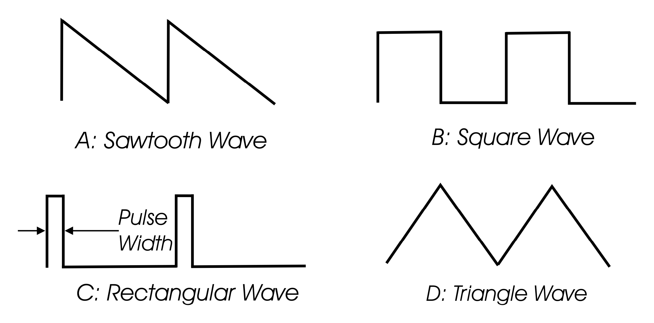
One basic waveform is the sawtooth wave. The start of the waveform’s cycle is a rapid jump from low to high then the waveform ramps down to the bottom. A sawtooth wave contains all the harmonics of the harmonic series, with the amplitude of each harmonic decreasing by the same ratio it increases, i.e. the 2nd harmonic is 2X the frequency of the fundamental, but 1⁄2 the amplitude of the fundamental. The rest of the harmonics continue in this manner. Because of all these harmonics, the sawtooth wave can be described as very bright and buzzy.
Another waveform is the square wave. A cycle of a square wave has two equally timed portions (the high and low), making it a symmetrical waveform. It has only odd harmonics (3X, 5X, 7X, etc), with each harmonic following the same basic amplitude relationship as the sawtooth wave (The 3rd harmonic is 3X the fundamental frequency and 1/3 the fundamental amplitude). The square wave sounds bright but also a little hollow (somewhat like a clarinet).
A square wave is a type of rectangular wave, it happens to be symmetrical. The width of the high portion of a rectangular wave is known as the pulse width, and can be expressed as a percentage. For instance, a square wave has a pulse width of 50%. When a rectangular wave is asymmetrical, it is called a pulse wave. As the pulse width gets much smaller or larger than 50% the sound becomes thin and reedy, yet bright. Pulse waves contain all harmonics, but the amplitude of the harmonics varies with pulse width.
A triangle wave is a symmetrical waveform. As it turns out all symmetrical waveforms have only odd harmonics. With a triangle wave the amplitude of the harmonics decrease much faster than a square wave (exponentially), which gives it a much mellower sound, closer to a sine wave than a square wave.
Hard Sync
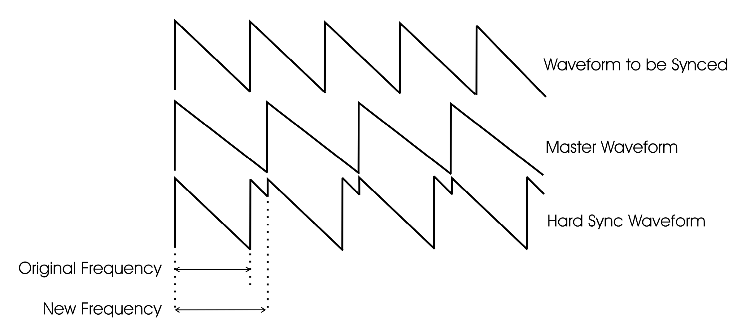
The term Hard Sync is a synthesis term that traditionally refers to resetting the start of an oscillator’s waveform at the frequency of another oscillator, called the Master Oscillator. It is called Sync because the oscillator that is restarted takes on the frequency of the Master oscillator, seemingly "synchronized" in frequency (see figure 13), yet with a new more complex waveform. The effect is strongest as long as the Master Oscillator frequency is lower than the oscillator that is reset. In fact, if the Master Oscillator is much higher in frequency than the synced oscillator, the synced oscillator signal becomes weak and possibly inaudible. This is a really important concept when using the FreqBox!
In the FreqBox, instead of using a second Oscillator as the Master, the signal at the input is used to reset the FreqBox’s VCO waveform.
This means the following are very important:
- The simpler the input signal, the cleaner and more predictable the Synced oscillator will be.
- If the input signal is not lower in frequency than the FreqBox VCO, then you may not hear anything at the output!
Hard Sync sounds are often aggressive in character, like hard distortion, especially if the waveform of the synced oscillator is a square wave. As you sweep the frequency of the synced oscillator, it sounds like you are sweeping through the harmonics of the master signal. A good example of a hard sync is the synth sound in the Car’s hit "Let’s Go".
FM
FM stands for frequency modulation. The term modulation refers to any process in which one waveform is changed in response to the contour of another waveform. Frequency modulation refers specifically to modulating the frequency of an oscillator. With a VCO, modulation is performed with control voltages. A very slowly, repetitively changing CV can modulate VCO frequency up and down and sounds like vibrato. If this signal is sped up to an audible rate (faster than 20Hz), the sounds produced are complex.
When we deal with audio rate FM, we refer to the modulated oscillator as the CARRIER, and the signal doing the modulation as the MODULATOR. In the FreqBox, the input signal is the Modulator, and the VCO is the Carrier. When the Modulator modulates the carrier’s frequency, new harmonics are generated. They are called sidebands. Sidebands exist above and below the frequency of the carrier at intervals determined by the frequency of the modulator. Not only do the frequency of the Carrier and Modulator combine to create complex sounds, the amplitude of the Carrier and Modulator also determine how many sidebands are audible. In a system like the FreqBox, where the amplitude of the Carrier is constant, the number of audible sidebands are determined by the amplitude of the Modulator. This means the timbre of the FreqBox will change with the dynamics of the input signal when using FM.
When the Carrier and Modulator are harmonically related, as in octaves or simple ratios, then the sidebands tend to be related, too. When the Carrier and Modulator are not simply related the results are quite clangorous, as the sidebands aren’t related harmonically to the input signal.
If this seems complicated, simply remember these points:
- You’ll hear the strongest FM effects when the Carrier is higher in frequency than the Modulator
- The mellower the Modulator and Carrier sound on their own, the simpler the FM results will be. Brighter sounding Modulators and Carriers make for dense and complex FM results.
- The loudness of the modulator affects the strength of the FM results.
- Frequency modulating an analog VCO with an audio signal can produce some wild and unpredictable results. Experimentation is key to discovering new timbres!
VCA
VCA stands for Voltage Controlled Amplifier. A VCA is an amplifier with the output level set by a CV. A low value CV (close to zero) turns off the output. As the CV increases, the output level increases too. This is used to control the loudness of a signal.
Envelope Follower
An envelope follower is a special type of circuit that detects the amplitude of a signal and generates a control voltage that varies with the amplitude. If the input signal is very quiet, then the output of the envelope follower is a very low voltage. If the signal is loud then this voltage is larger.
In the FreqBox the envelope follower is routed to modulate the frequency of the VCO. Since the envelope follower follows the dynamics of your instrument's signal, you can actually 'play' the VCO as you play your instrument – the louder you play the higher the VCO frequency.
In the FreqBox, the VCO output is sent to a VCA that is also modulated by the envelope follower. This allows the dynamics of your playing to control the loudness of the VCO signal, so that when there is no input signal you can’t hear the VCO at the output, even though it is always oscillating. Because the envelope follower is using an audio signal for detecting amplitude, it is normal for a small amount of "ripple" to ride on the envelope follower CV. The ripple is also related to frequency, such that there is more ripple on low notes than high notes. Note that some instruments have really complex tonal characteristics that may cause a lot of ripple. For instance some hollow body guitars and acoustic guitars have resonances that create peaks in their frequency response. These can mean that the envelope follower will have a great deal more ripple. It is normal in the FreqBox to hear a little of the ripple amplitude modulating the VCO if the Sync switch is OFF, especially from low notes played on your instrument.
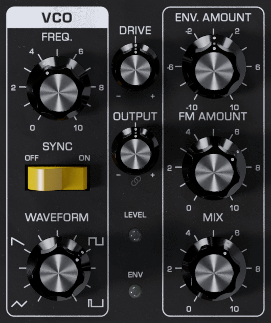
TOURING THE FRONT PANEL
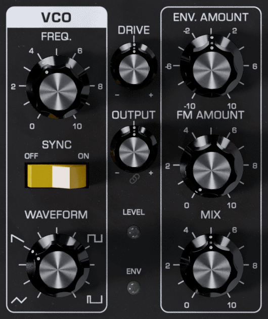
The VCO Section
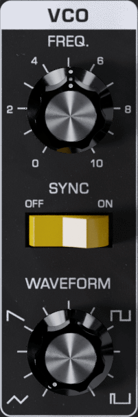
The WAVEFORM control is used to set the waveform of the VCO. The legend around the control indicates approximately the locations of the waveforms. The basic waveforms are: triangle, sawtooth, square, and pulse. A triangle wave is produced when the control is fully counterclockwise. As the control is advanced clockwise, the waveform is crossfaded to a sawtooth, then to a square wave, then to a pulse wave.
The SYNC OFF/ON switch engages the FreqBox’s hard sync function, causing the VCO to be retriggered by the input signal. If the input signal has a simple waveform, then the VCO will be retriggered at the frequency of the signal. A very complex signal (like a dissonant chord) will cause less predictable results, as the VCO will be retriggered not at a predictable frequency but by the sum of all the frequencies.
A pitched tone may or may not be the result. With guitars, if a note is plucked hard and left to ring, there are times when the second harmonic is louder than the fundamental. You may hear this as the VCO tone will shift with this change. If the VCO frequency is much lower than the input signal, it is possible that you won’t be able to hear any output from the VCO, especially if the waveform is a square wave, or pulse wave.
The FREQ control is used to adjust the frequency of the VCO. If the ENV AMOUNT and FM AMOUNT controls are set to 0 and the SYNC is OFF, the frequency of the VCO is nominally 25Hz if it is fully counterclockwise. When it is fully clockwise the frequency of the VCO is nominally 1.6KHz, or 6 octaves higher.
The Modulation Section
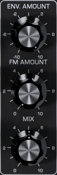
The ENV AMOUNT control sets the amount that the envelope follower CV is applied to the VCO frequency. Note that the envelope follower CV is ADDED to the setting of the FREQ control with ENV AMOUNT set above 0 and is SUBTRACTED from the FREQ control setting when ENV AMOUNT is set below 0.
The VCO frequency can be swept by the envelope follower CV over 8 octaves, more than the FREQ control on the front panel. Be aware that the setting of the ENV AMOUNT control depends a great deal on the setting of the DRIVE control, as it is the drive signal that is used to extract the dynamic information. The optimum setting of the drive control is such that average levels cause the Level LED to light mostly Yellow-Orange, and peak levels might cause a little red. If the DRIVE control is cranked for distortion, then the performance of the envelope follower is reduced in responsiveness as the drive signal is compressed somewhat from the clipping of the signal.
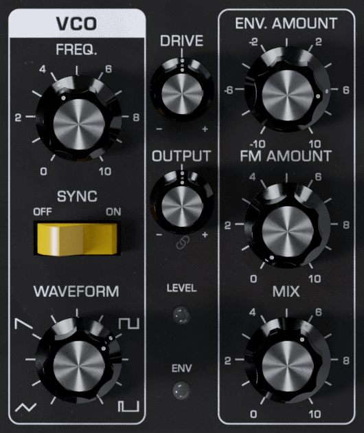
The FM AMOUNT control is used for setting the amount of the drive signal that frequency modulates the VCO. When the FM amount is all the way counterclockwise, none of the drive signal modulates the VCO. As the control is turned clockwise, the amount of FM increases. Note that because the depth of FM is also related to the strength of the drive signal, the Drive control and the dynamics of the input signal affect the depth of the FM. For a stronger maximum FM effect, increase the Drive amount. The type of input signal has a significant impact on the output when using FM. The simpler the input signal’s waveform, the more predictable the results will be. A more complex input creates more sidebands and thus a more chaotic sound. The waveform of the VCO also has a great deal to do with the results, as the brighter waveforms (saw, square, and pulse) create a lot of harmonics.
The MIX control sets the balance of drive signal to VCO signal. When the MIX control is fully counterclockwise, the output is 100% the input signal. When the MIX control is in the center the output is 50% input signal and 50% VCO signal. When the MIX control is all the way clockwise, the output is 100% the VCO signal.
Audio and Level Control

The DRIVE control and the LEVEL light are part of the audio input level circuitry.
The DRIVE control adjusts the input gain. With this control you can set the right input gain for virtually any instrument or line-level signal source. Turn this control counterclockwise for strong input signals, and clockwise for weaker sound sources.
The LEVEL light tells how strong the input signal is after being adjusted by the DRIVE control. As the signal level increases, the light goes from off, to green, to yellow, and finally to red. Very weak signals do not light up this light at all. When the light is green, the signal is below the level that results in audible distortion. When the light is yellow, some low order distortion may be audible, giving the sound a subtle warm analog quality. When the signal is strong enough to drive the light into the red, the distortion at the output becomes stronger and more distinctly audible. Watch this light when you set the DRIVE control for the desired effect.
The OUTPUT control provides positive and negative gain for the final output of the effect, after the drive and modulation. This allows you to dial in the amount of drive and saturation you want for your sound while keeping the signal level in a good range for further processing.
The LINK button just below the OUTPUT control links the DRIVE and OUTPUT controls; as you turn one control up, the other is automatically turned down in order to maintain unity gain through the effect.
Switches
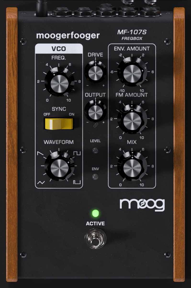
ACTIVE – Controls whether audio input is sent into the delay line. When the ACTIVE light is green, the delay is active. When the ACTIVE light is off, the audio input is passed directly to the output and is not sent into the delay line.
NOTE: When the effect is not active, the CV outputs still continue working, to fully disable the pedal, use the bypass feature that your DAW provides
Advanced Applications
The FreqBox is a natural for using with other effects. It is the perfect type of signal to run into a filter because it can produce the basic waveforms used for subtractive synthesis. Filter effects include the MF-101S Lowpass Filter, the MF-103S 12-Stage Phaser, and the MF-105S MuRF (Multiple Resonant Filter Array). A MF-104S Analog Delay is also a good choice, as it has some really nice filter characteristics and delay can really fatten up the VCO sound. If you find the FreqBox to be too dynamically sensitive for your style of playing, or too dynamically sensitive to your instrument, try putting a distortion device or compressor before the FreqBox. This will have the effect of compressing the FreqBox VCO as well as providing more sustain.
ADVANCED PLUG-IN FEATURES
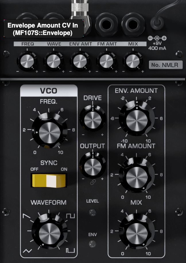
The MF-107S offers additional functionality beyond the panel controls. To access, click the Settings icon ![]() in the top right of the plugin window. Click the row of CV jacks across the top of the pedal or the "CV" button next to the Settings icon to display the “back panel” of the MF-107S, showing the modulation input controls.
in the top right of the plugin window. Click the row of CV jacks across the top of the pedal or the "CV" button next to the Settings icon to display the “back panel” of the MF-107S, showing the modulation input controls.
Modulation Inputs

The original Moogerfooger effects provided input jacks for voltage control of the parameters, using expression pedals or other control voltage (CV) sources connected in classic modular synth style. The MF-107S brings this dynamic connection concept to the world of plug-ins, by providing virtual “CV Ins” which you can connect between any instances of any Moogerfooger Effects Plug-ins within your project.
NOTE: CV connections are stored in your DAW project, but not in the presets of each Moogerfooger Effects Plug-in.
The MF-107S offers CV Inputs to modulate the VCO Frequency [FREQ], VCO Waveform [WAVE], Envelope Amount to VCO [ENV AMOUNT], the FM Amount [FM AMOUNT], and the Mix [MIX]. Click on one of these CV IN jacks to see the connection options which are available.
TIP: As with the original Moogerfoogers, you can connect a pedal to itself to create more interesting sonic interactions than what's available on the front panel!
A list of all Moogerfooger Effects Plug-in instances which are active will appear in the drop-down menu, as well as the modulation sources they provide. Each plug-in instance is identified on this menu by a unique, randomly generated four-letter code. The same code is displayed on the “back panel” UI of the plug-in itself, in the lower right corner of the CV Input jack panel. This allows you to distinguish between multiple instances of the same plug-in. Choose any modulation source to make a connection.
The strength of the selected modulation is controlled by a bipolar knob below each CV IN jack, with zero (no modulation) in the center, increasing positive modulation if you turn the knob to the right, and increasing negative modulation if you turn the knob to the left.
TIP: Double clicking on the attenuator knob will reset it to zero.
Above the list of Moogerfooger Effects Plug-in instances are a handful of additional options and input sources:
- None - will remove any connections currently made to this CV input.
- Bipolar - will be available as an option if the chosen modulation source (an LFO for example) can be bipolar - centering the modulation around the current knob value.
- DC - provides a DC offset that you can scale with the associated attenuator. Since the CV attenuator itself can be automated or MIDI mapped, you can use this like an expression pedal. It will provide the same range of automation/modulation to a parameter regardless of any presets you choose.
- Side Chain - allows you to use an independent audio signal from another track as a modulation input. You can select either the Left or Right Input from stereo signals. Your host software will see the Side Chain Input as an additional input to the plug-in, which you can connect to the audio source of your choice.
NOTE: The CV side chain is designed to take DC-coupled analog or digital CV signals - regular audio signals might yield surprising results.
Visualizing Modulation
Making a CV connection will insert a virtual 1/4" cable into the top of your Moogerfooger (which can also be seen when you expand to see the back panel by clicking "CV" or the row of jacks across the top of the pedal). The incoming modulation signal will be seen in yellow on the connector. Additionally, the knob corresponding to the parameter being modulated (if present - not all parameters have a corresponding knob) will show a white circle indicating the current value due to modulation.
Settings
OSCILLATOR
The original MF-107 was a mono effect, featuring a single oscillator that would track a mono signal. The MF-107S features a STEREO mode with two independent oscillators for the left and right channels to preserve the stereo image of your audio tracks. With the OSCILLATOR switched to MONO the MF-107 uses the same oscillator for the left and right channels. In both modes, the envelope follower remains mono.
ENVELOPE CONTROLS
On the original MF-107 the onboard envelope follower controlled both the level of the FreqBox effect and the frequency of the VCO (adjustable with the ENV AMOUNT control). With the MF-107S you can preserve this behavior with the Envelope Control setting switched to FREQUENCY AND LEVEL. By switching to FREQUENCY ONLY, the FreqBox effect will always be on - creating a droning sound.
Additional UI Interactions
Double-click any control to reset it to its default position.
Hold the CTRL key while adjusting any knob for more precise fine-tuning.
PRESETS
In addition to your host software’s plug-in preset management system, the MF-107S provides an easy-to-use, built-in browser for selecting and saving presets.
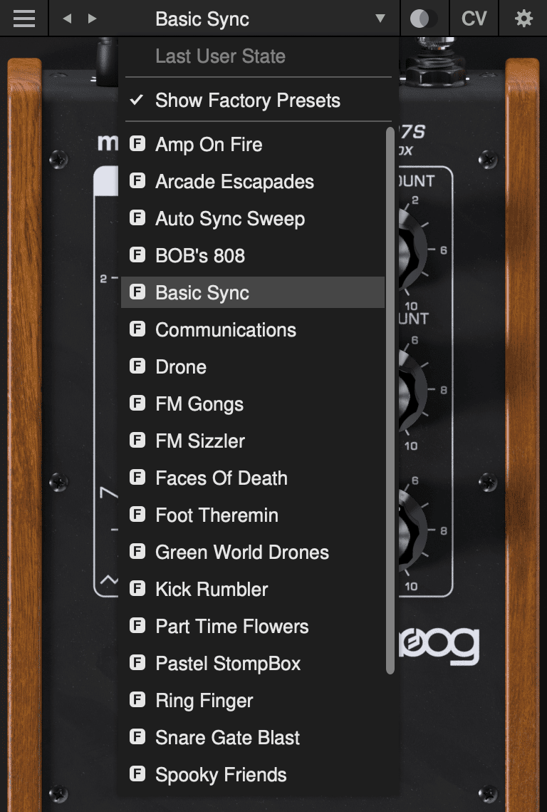
The currently selected preset name is shown at the top of the plug-in UI window. Click the left and right arrows to the left of the preset name to scroll through the preset list. Click the down arrow to the right of the preset name to expand the list and view all presets.
Last User State
The top option on the preset drop-down menu is Last User State. If you load a preset at a time when you had made changes to the plug-in settings which were not saved, your unsaved changes are automatically saved as the Last User State. This allows you to easily compare an existing preset with some new settings which you are still dialing in, or to go back after a preset change without losing your work. Only the most recent unsaved User State is captured in this way. An unsaved User State is indicated by an asterisk (*) to the left of the active preset name.
Show Factory Presets
Some people love the convenience of factory presets; others prefer to use only their own custom settings in their music. You can choose to hide the factory presets and show only your own original presets in this drop-down list by unchecking Show Factory Presets. If Show Factory Presets is checked, then all presets including the factory set will appear in the list. Factory presets are indicated by an F icon to the left of the preset name.
Compare Switch
Directly to the right of the preset drop-down is the Compare switch, which switches between the last loaded state and the last changed state. Load a preset, play around with it, and then click the Compare switch to toggle between the preset loaded and your most recent modifications to it.
Presets Menu
The Presets Menu is located in the top left corner of the plug-in UI window. Click the ![]() icon to show the Presets Menu. The following options are available:
icon to show the Presets Menu. The following options are available:
- Init Preset – creates a new INIT preset as a starting point for sound design.
- Save Preset – saves the current state to the currently-active preset. Overwrites the previous state of that preset.
- Save Preset As… – saves the current state as a new preset with a new name.
- Delete Current Preset – deletes the currently-active preset. Factory presets cannot be deleted in this way.
NOTE: You can also drag and drop preset files onto the plug-in UI to import them automatically.
- Export State - allows you to choose any folder in your computer’s file system and save the current plug-in state as a new preset in that location (Save Preset and Save Preset As will automatically place saved presets in the plug-in’s own Presets folder).
- Open Presets Folder - opens the plug-in’s Presets folder on your system’s desktop (Finder or File Explorer).
- Open Manual - opens this manual in your web browser.
- Contact Us For Help - opens the Moog Music customer service website.
SUPPORT
Moogerfooger Effects Plug-ins are designed for macOS 10.13 / Windows 10 systems or newer.
VST3, AudioUnits, and AAX plug-in formats are supported.
Should you experience any issues with your Moogerfooger, please contact [email protected].